Basic throttle settings
Before you start, you should check what is:
Throttle
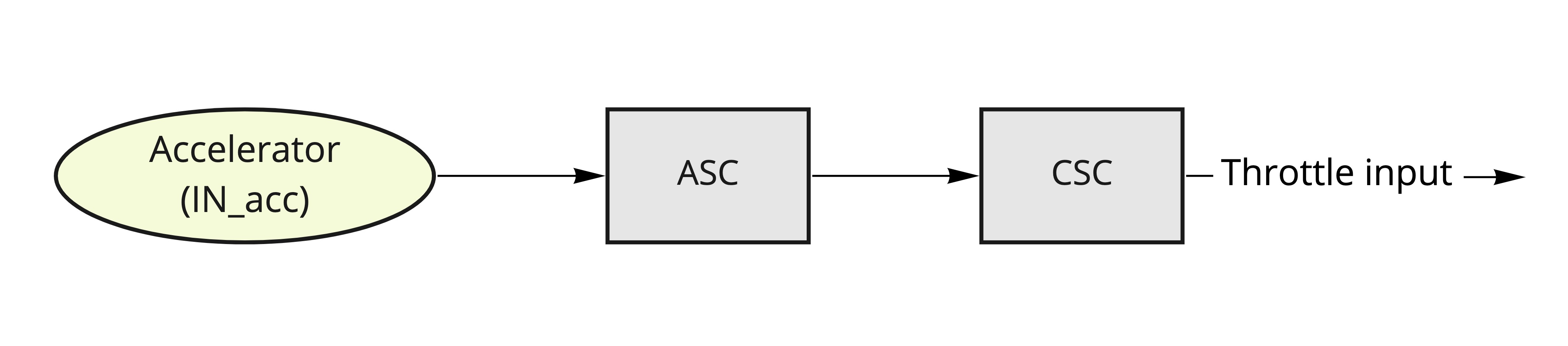
Generic analog throttle input. The signal is normalized in ASC block: this converts the input signal from [mV] to normalized value 0-1. After it is shaped in CSC block (to add low pass filter or deadzones).
Throttle signal flow:
Configuration steps
Setting throttle input
The LYNX allows you to use different GPIO input pins for the throttle signal. This is done by setting the parameter /io/IN_acc to the GPIO ID of the throttle signal.
This is a list of most common GPIO pins:
/io/IN_acc value | Input name |
|---|---|
| 8 - default | GPIO0 |
| 9 | GPIO1 |
| 10 | GPIO2 |
| 11 | GPIO3 |
| 12 | GPIO4 |
Check the Input mapping for more information.
Also it is recommended to configure the GPIO to the floating input (disable pull-up or pull-down resistor). This can be done by setting the /common/ioconfX parameter to 0. More about ioconf here
Setting throttle signal range
Check the getting started guide for the first steps with the LYNX: Getting started - throttle
For setting the throttle signal range, you can use the /acc/asc folder. The most important parameters are:
min- minimum value of the throttle signalmax- maximum value of the throttle signal
For setting the throttle deadzones, you can use the /acc/csc folder. By default, the 10% from the signal range is set as a deadzone. The deadzone is at low and high values of the throttle signal.
- Check the
ldzfor the lower deadzone - Check the
hdzfor the higher deadzone